2. Screen-Space effects in EEVEE
2.1. Intro
Custom screen-space effects (a.k.a. “Filters” or “Post-Process FX”) can be used to add some awesome visual flare to scenes and animations, but blender (and EEVEE specifically) is generally lacking in this department, as the Compositor isn’t really designed for complex effects and of course isn’t viewable in realtime.
Blender devs have talked about Viewport Compositing as a feature milestone for a while, but for now it’s not a high-priority task and isn’t even in the planning stages as of writing this (as far as I know).
Thankfully, EEVEE does have one post-process shader which we have some control over - Screen Space Refraction. Due to being wrapped up in a PBR shader node, it’s not super easy to work with, but with a bit of wrangling we can at least extract colour information, and add distortion in screen-space.
I won’t go too much into the specifics of how SSR is implemented in EEVEE, but there are some limitations related to that which it’s good to be aware of so I will cover it a little.
2.2. Overview
- In this tutorial we’ll go through the process of:
Setting up Screen-Space Refraction settings for a Scene and Shader
Creating some utility node-groups to make working with the shader easier (reduce the amount of maths!)
Creating a couple of Sci-Fi glitch FX, and some basic distortion shaders to showcase some examples.
As usual, it’s a good idea to enable the Node Wrangler addon!
2.3. Setting up Screen-Space Refraction (Scene/Material)
SSR must be enabled in both the Scene render settings, as well as the shader itself.
2.3.1. Render Settings:
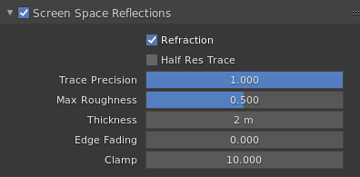
Enabling
Refractionis necessary of course, DisablingHalf Res Traceenables rendering the refraction pass at full resolution (by default it is rendered at half resolution and upscaled) and will slightly increase quality for a relatively small performance cost.Trace Precisionaffects the ray marching algorithm itself, usually you won’t notice a performance hit from setting it to 1.Max Roughnessis another optimization which disables Refraction for shaders above the roughness value - we’ll be using a roughness of 0 so this doesn’t apply here.Thickness- without getting too complex, this is how much geometry in the scene is “Extruded” away from the camera (since it’s a screen-space effect, it doesn’t know what’s behind the first layer of geometry visible). We’re going to set it relatively high to prevent holes when doing heavy distortions.Edge Fading- again, since this is a screen-space effect, if you attempt to distort pixels which aren’t visible (e.g. off screen) they will be replaced with the world background color. I prefer to turn the fading off entirely to get more mileage out of it.Clamp- This just clamps the max brightness of reflected/refracted pixels, not really relevant here.
2.3.2. Material Settings:
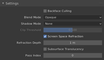
Backface Cullingdoesn’t actually affect us, since SSR only supports 1 “layer” of refraction. Leaving it off lets us use both sides of planes to refract so let’s keep it off.Blend Mode- Opaque, since the Refraction basically simulates transparency anyway.Shadow Modeis set to None since we don’t want our screen-space filter casting shadows on the scene.Screen Space Refractionis the obvious important one which must be switched on!Refraction Depthis a bit complicated, set it to something reasonable like 1 for now. We’ll come back to this one later!The remaining settings aren’t used here.
2.4. Aside: Refraction concepts
Before we go any further, it might be a good idea to explain (at least approximately) what we’re going to be doing with the refraction, and what the Refraction Depth value I skimmed over earlier is for.
In the real world, when light hits a transparent object with a higher Index of Refraction (IOR) than air (which has an IOR of 1), it’s bent or refracted towards the normal of the surface it hit. When it leaves, (passing from a high IOR to a lower one) it’s refracted in the opposite direction, away from the normal, and continues roughly along its original path, as shown in the image below (public domain c.o. wikipedia)
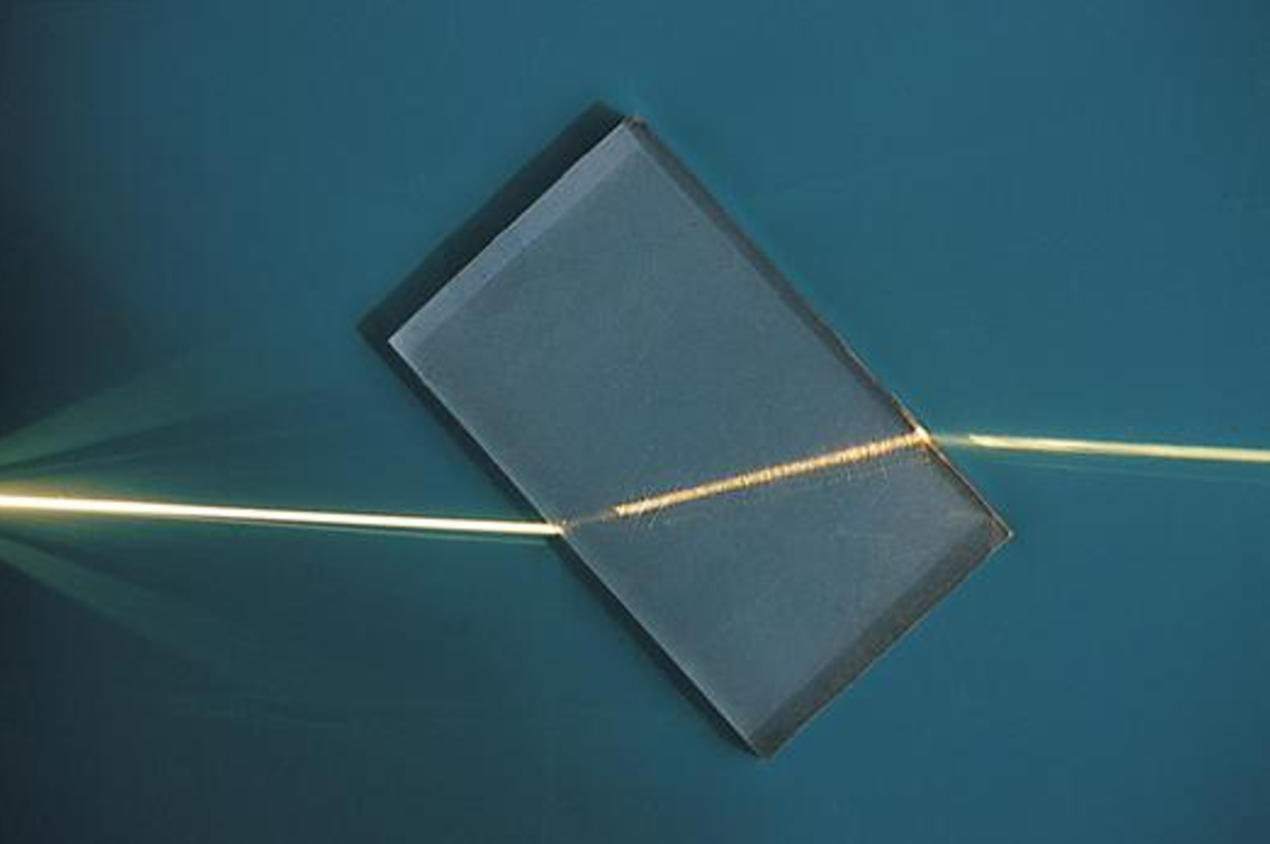
You can see how the light ray leaving the block is parallel to the ray entering, but offset to one side. How far the ray is offset depends on how much material it passed through between entering and leaving the block - this is the Refraction Depth property referred to by EEVEE.
If the Refraction Depth is set to 0, that actually tells EEVEE that the object is “infinitely thick”, and that once a ray enters it never leaves (so the ray is only “rotated” once, and not bent back since it never exits the material). This is useful for things like water planes, where the objects behind the mesh are supposed to be “in” it.
In our case though, we want to only offset rays to the side, not rotate them, so we set the thickness as high as we can to get the most sideways displacement range we can manage. You’ll notice if you turn the thickness up too high it’ll start clipping through things, so you’ll want to adjust it as you go along.
2.5. Basic Screen-space offset shader
Let’s start with something simple, a shader which lets you offset pixels by some amount in any direction!
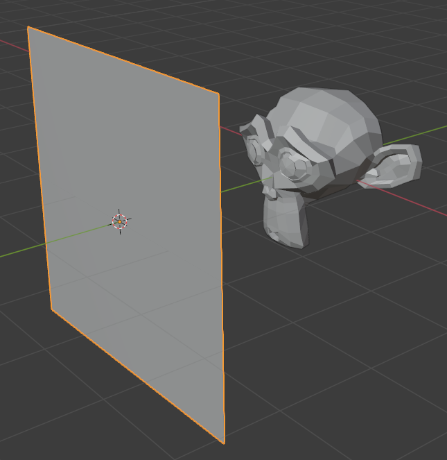
Our scene will just be some object with a plane in front, and we’ll apply our Refraction shader to the plane, like so:
In the node editor, add a Refraction BSDF node, set its colour to white (it’s a light grey by default), set its IOR to 2, and plug it into the output.
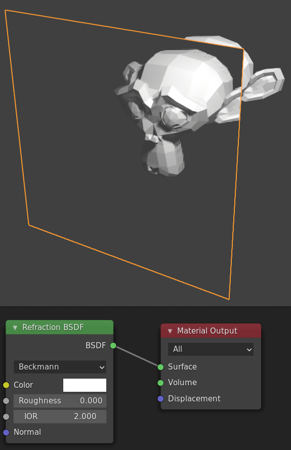
Right now we have what’s basically a slightly exaggerated pane of glass, making things on the other side look a little closer than they really are.
Next we’ll want to start breaking the laws of physics to make fun effects! Let’s start by setting the Normal of the surface to just be the angle we’re looking at the surface from, i.e. the Incoming vector of the Geometry node. Let’s put a vector Add node in between so we can play with the value as well.
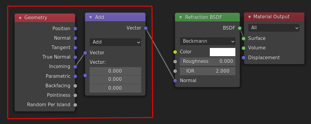
Now, if we play with the offset values we can very crudely “displace” the image we see through the surface, like so:
You may notice that all our vectors are currently in world space. The Refraction BSDF shader takes the normal input in world space, but for the types of effects we’re doing it’s probably more useful to use screen-space vectors, so let’s do that next.
Thankfully this is just one node, a Vector Transform from Camera to World:
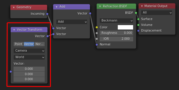
Now the X and Y components in the input vector (to the Vector Transform) correspond to horizontal and vertical in the viewport.
2.6. Example: Simple distortion shader
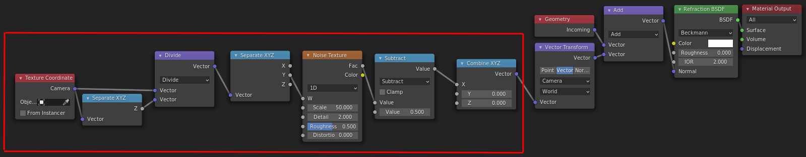
Before we add more complex effects, here’s a very simple shader you can make with only what we’ve built so far.
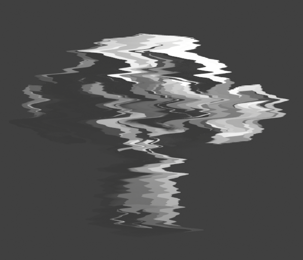
It uses a 1D noise along the screen Y axis to offset things on the screen X axis. I use Camera texture coordinates rather than Window since they’re the same independent of aspect ratio (things will look the same in the camera view as in the viewport), although you need to divide by the Z component to remove the warping caused by the perspective projection, in order for textures to look “2D”.
The noise is subtracted by 0.5 to make it displace equally to the right and left, otherwise it offsets everything to one side as you might expect.
2.7. Chromatic Aberration (Colour separation) shader
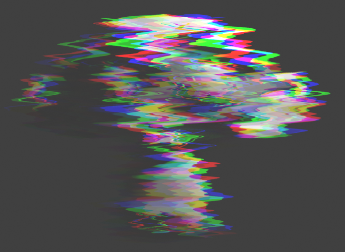
What we’ve got so far is great for simple distortion effects, but another great use for this is “glitchy” effects, and a common occurence in these types of effect are colour separation, like we have here:
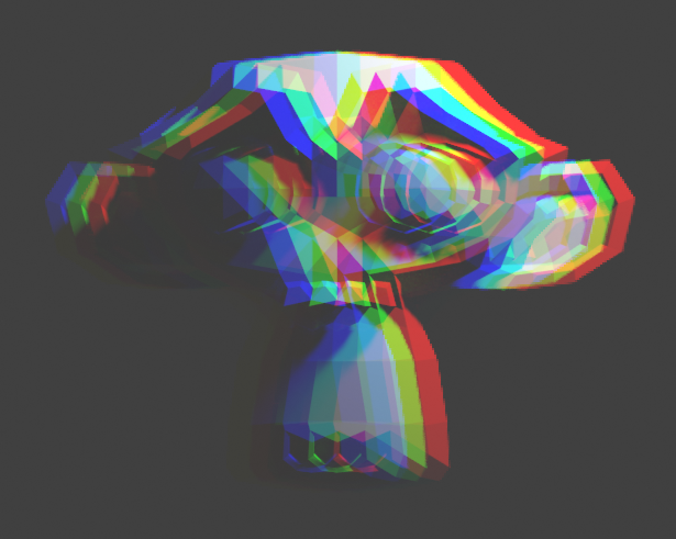
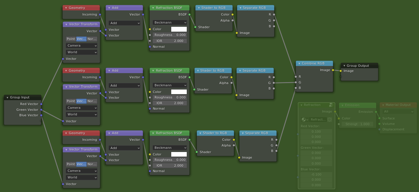
This is quite easy to do as well - all we need to do is use a separate refraction shader for each of the Red, Green, and Blue components of our output color.
For now let’s just duplicate what we’ve got so far 3 times, and use the handy Shader to RGB node to actually retrieve the color of the pixel we’ve refracted. Then we can use the Red component of one, the Green of another etc. to offset each color separately.
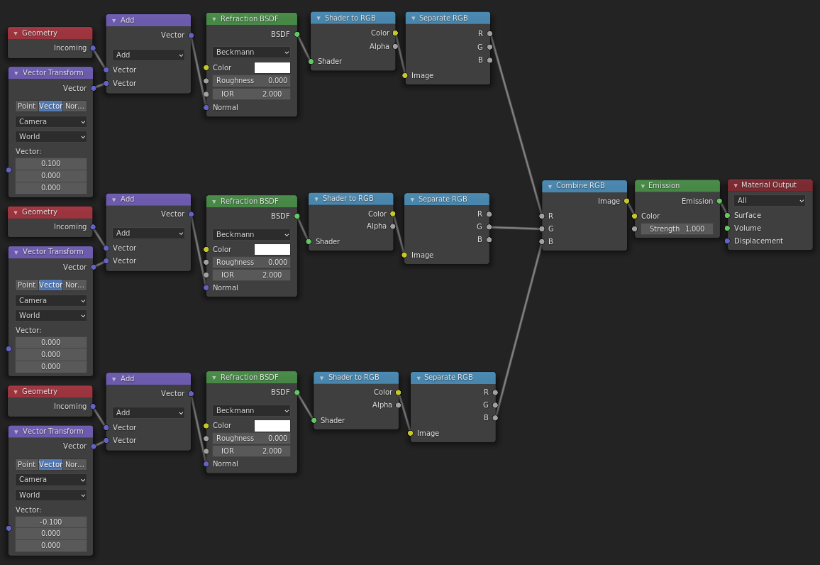
To make things a bit neater, let’s group all these nodes together into a single nodegroup with 3 Vector inputs and one Color output, so we’re left with something a little like this:
2.8. Example: Colourful distortion shader
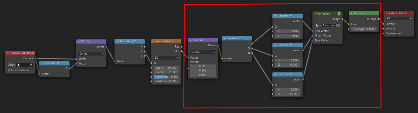
Let’s make our distortion shader we made earlier a little more interesting by separating the colours.
We’ll modify the one we made before - instead of using the Fac output, we’ll use the Color output of the noise texture node to get 3 separate values, and plug each of those into the X offset for our 3 colours, like this:
If you turn down the strength of the noise (with the Scale vector math node) and animate an offset by using a driver in the Value node (type in #frame / 50 as the input value for example), you can get quite a nice “old VHS tape” look (Or at least one aspect of it).
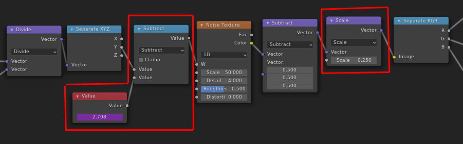
which gives us this:
2.9. Example: Blocky Glitch FX
For a final example, let’s make a more “digital” looking glitch effect.
As it turns out, this is also very easy - we can just replace our continuous noise texture with a blocky one!
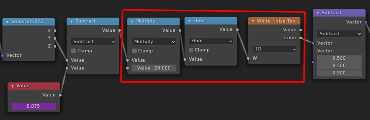
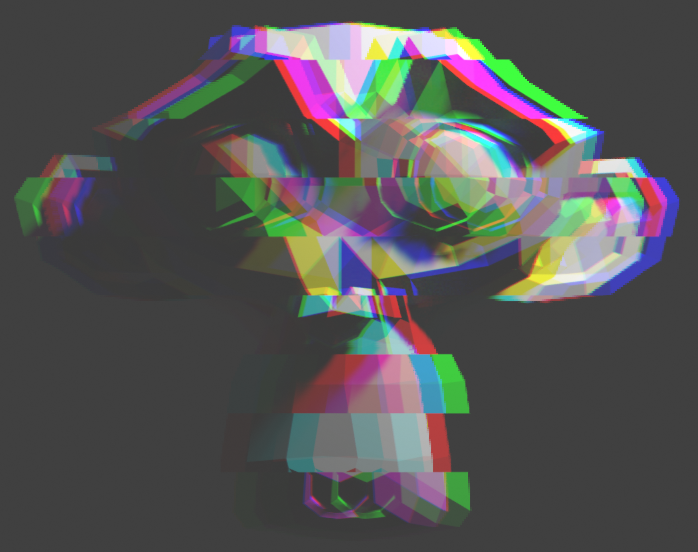
And with just that very quick change, we’ve now got a blocky, chopped up image:
This is alright, but actually doesn’t look that good. I’ve found that it looks better when only the Red and Blue channels are distorted, as a more subtle effect is less rainbow-pukey. You can play around with different multipliers for channels, flipping them, masking out the effect so it is only sometimes active etc.
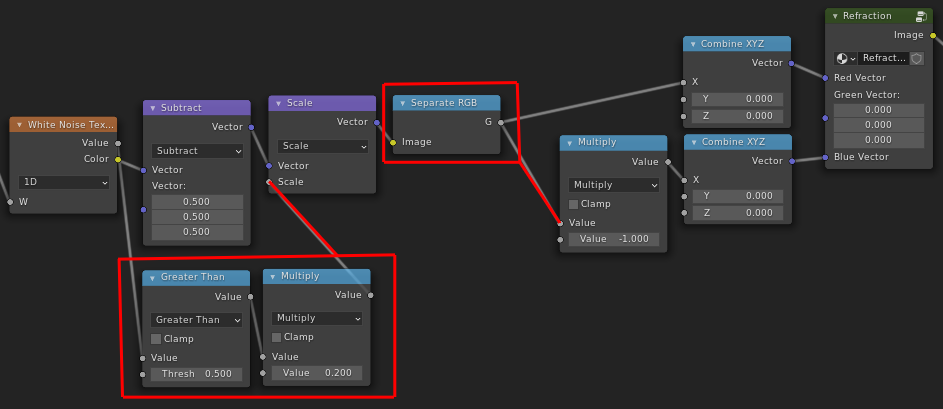
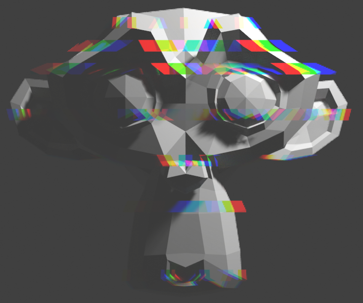
Here I masked out the effect when the noise value is less than 0.5 (so half the time), and made the Blue channel the inverse of the red channel, so it’s always offset in the opposite direction.
2.10. Finishing off
It still doesn’t look particularly fancy, since I wanted to keep the examples fairly simple, but hopefully this can inspire you to come up with some sweet FX of your own!
Here’s a few I’ve made over the last while and while writing this tutorial, I’d really like to see what people can make with this so please tag me if you make something cool!
https://twitter.com/lateasusual_/status/1354163912971792384
https://twitter.com/lateasusual_/status/1341552615373631488
https://twitter.com/lateasusual_/status/1353440424447406081