1. Realtime 3D Spiral Noise FX
1.1. Intro
I decided to make a written tutorial rather than a video, partly because it’s much less work, but also because I personally much prefer to follow text+image based tutorials where all the information is available, than a video tutorial you have to watch through several times to unpack everything.
If you’re new to noding in blender, here are a few things which might help you out when copying nodes from pictures:
If you see a node with a
Light BlueorPurpleheader, and with a drop-down menu in the middle with the name of the node (e.g. a node namedAddwould have anAddbutton in the middle), then it’s aMathorVector Mathnode respectively.The
Node Wrangleraddon comes bundled with blender (go to to enable it). Node wrangler comes with a heap of features, but the one I use the most isCtrl+Shift+Clickon a node to preview its output.If you’re working on heavy shaders they might take a while to compile. This can get annoying if you’re changing lots of things at once, so using
Ctrl+Spaceto fullscreen the node tree (or setting the viewport back to solid mode) can help speed up node work.
If you’re not interested in nodes and only want codes, you can skip down to the Extra: Example BEER GLSL Shader section.
Or, if you want a completed file with some extra additions, I’ve put one up on gumroad.
1.2. Overview
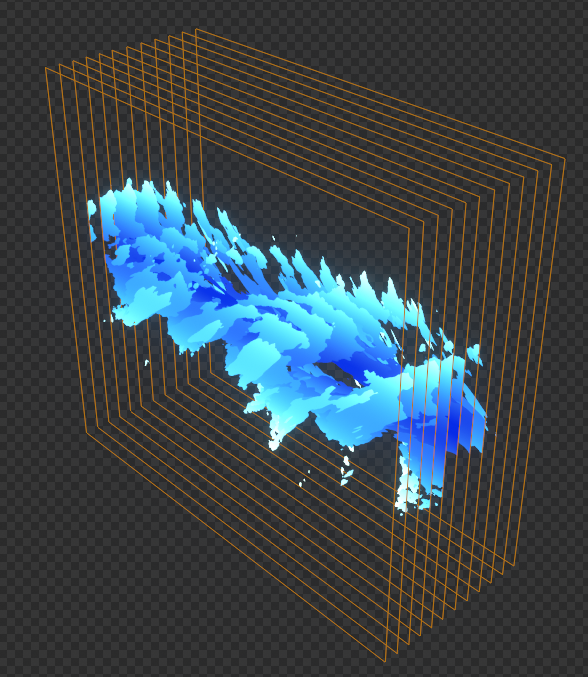
The main technique behind the effect (when using shader nodes - more on code later) is using stacked planes to mimic ray-marching. If we can make a 3D function that describes the effect we want, we can take a bunch of “slices” through it at regular intervals.
If we’re going a bit deeper and programming the effect (e.g. in GLSL, HLSL, or a Unity Shader) we can take advantage of some simple loops and vector math to do the “slicing” in the shader itself (A very basic form of Ray marching)
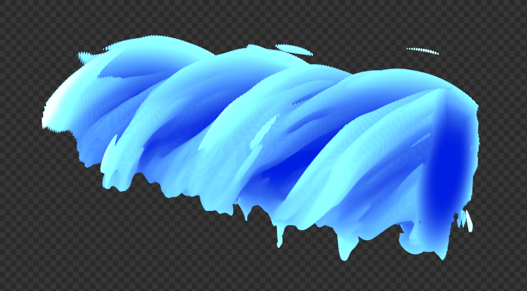
Here’s an example of the effect with the number of slice planes trimmed right down to make it clearer:
So, without further ado, let’s start from the bottom and work our way up! I’ll cover the process with Blender (EEVEE) nodes first, and then give a very brief explanation of the GLSL code at the bottom.
1.3. Step 1: Mesh Setup
The mesh is just a stack of planes, but since we want to make it riggable we need to be using UV’s instead of object space coordinates for our textures, which adds a few extra steps. If you’re not interested in deforming the mesh, you can skip the UV steps here.
Starting with a new, empty Blender scene, first demolish the default cube and replace it with a plane mesh. In Edit Mode move the plane down by 1 unit.
Add an Array modifier to the plane, set any default offsets to 0, then set the Constant Z offset to be a driver with the modifiers Count input as the target, and with the expression 2 / count.
Hint
You can right click -> Copy As New Driver to quickly grab driver targets, as shown above. Right click -> Paste Driver to apply it to properties.
Once you’ve done this you’ll be able to easily change the number of slices we take by just changing the Count property of the Array Modifier like so:
Note
The equation x / count will break if count is 0 - If you accidentally drag the count to 0 the drivers may break until you update them or reload the file. If this gets annoying you can replace count with max(count, 1.0) to prevent dividing by 0.
As well as the main Z offset driver, we’ll also want to add a driver to the UV’s - this is a way for the shader to “know” which plane we’re on, which will be needed later to make the shader deformable.
Add the same count driver as before, but this time with the expression being just 1 / count

We’ll also need 2 UV maps (we need 3 axes, so there will be one spare), so add these to the plane mesh as well. I’ve called mine XY and Z_ to help remember which axis is which.
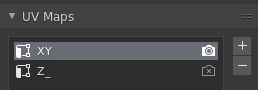
The XY map should just be the default for the plane (a big square). The Z_ map should be scaled down to 0 like so:
That’s everything for the mesh setup for now. You might want to turn the object on its side (rotate around the X axis) for a better viewing angle, and scale it along the X axis (In Object Mode) for a more rectangular shape.
I’d advise to keep the count of the Array Modifier somewhere around 100 while working to avoid performance problems!
1.4. Step 2: Shader Setup - Texture Coordinates
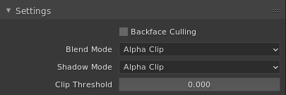
Add a new Material to the plane mesh, and enable Alpha Clip for Blend Mode and Shadow Mode.
Next, we’re going to add the Texture Coordinate inputs to our shader. If it doesn’t need to deform, you can just use the Object output from the Texture Coordinates node, but we’re going to use the UV’s we set up earlier to recreate Object Space coordinates, but which deform along with the mesh!
The full texture coordinate input setup is as follows:
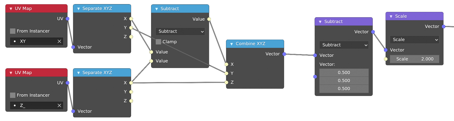
Ideally, this would be as simple as taking the X and Y outputs from the XY map, and using the X output of the Z_ map as the Z component of our vector, but it’s not that simple. The Array Modifier UV Offset affects every UV Map, so our X input is skewed! Thankfully we can just subtract off the Z component to straighten it back out again.
Finally we subtract each component by 0.5, and multiply by 2 to remap our 0..1 range back to -1..1
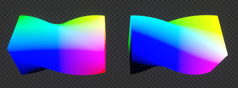
The reason we use UV maps here instead of Object Space coordinates isn’t obvious here, but once you deform the mesh it becomes apparent why we need it (Object Space on the left, our new UV-based coordinates on the right):
Hint
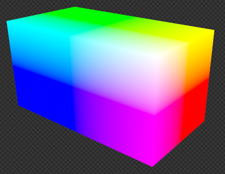
Here I’ve plugged the vector output straight into the output of the shader. This is really useful when working on shaders to preview what your texture coordinates look like! As you probably can tell, XYZ maps to RGB.
As you can see the Object Space coordinates don’t deform with the mesh!
At this point our shader looks like this (remember we’ve rotated the cube on the X axis - so Z/Blue is facing towards us):
Next we’ll start working on the shader itself.
1.5. Step 3: Shader Setup - Basic 3D Shader
Let’s start with some simple 3D output, so we’ll be able to see what we’re working on. Add these nodes onto the coordinates we generated in the previous step:
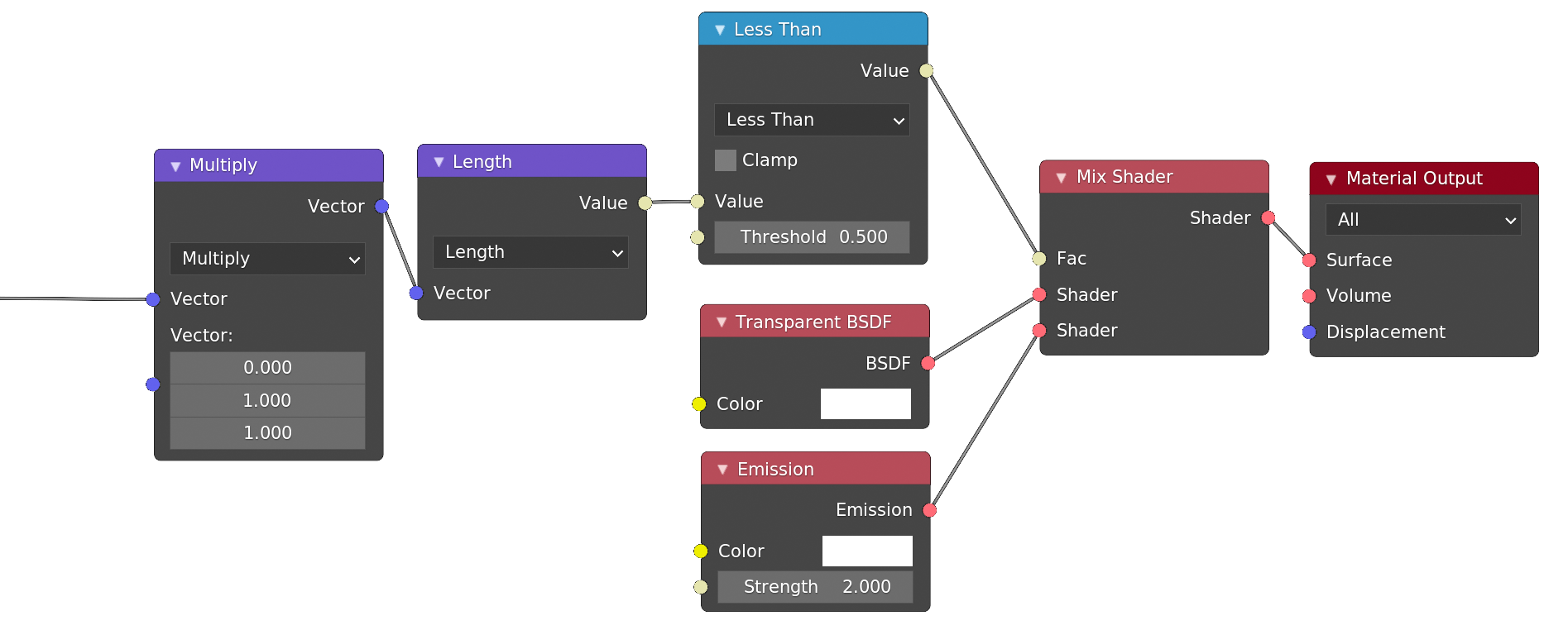
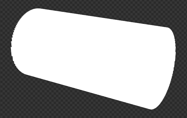
The Multiply node masks out the X component of the input vector, and so taking the length of that gives us the distance to the middle of a cylinder aligned with the X axis. Then we’re saying “If the distance to the middle is less than 0.5, use an Emission shader, otherwise use a Transparent shader,” and we get a blank white cylinder like this:
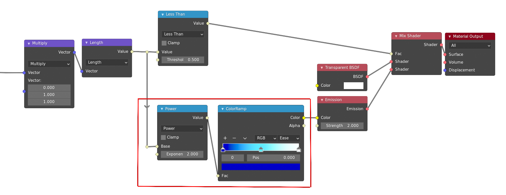
We’re starting to see a 3D shape emerge, but it’s quite difficult to see what’s going on when it’s all a blank white, so let’s add our simple “shading” now. We can use the distance to the center of the cylinder to control the colour - make the middle a dark blue and have lighter tones around the edges, with white splashes on the outside:
Hint
Hold Shift and Right-mouse-drag (or Ctrl+Shift+Left mouse if you’re a left click select heathen) over node links to add reroute nodes if you want to keep things tidy.
The Power math node is just to give a slightly more pleasing gradient - you can tweak it or remove it completely if you want to change the look of the colours.
This way we get a much clearer view of things (and this is pretty much all we need to shade the final result).
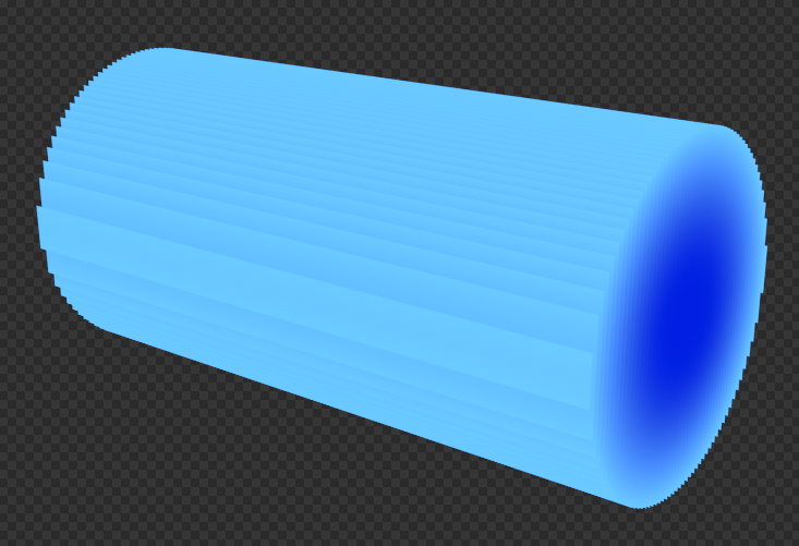
There’s some very obvious banding here - this is one of the downsides of this technique, but it’ll be a lot less noticeable once we start adding the rest of the shape.
1.6. Step 4: Shader Setup - Noise
Next we’ll add use some noise to add variation to the width of our cylinder:
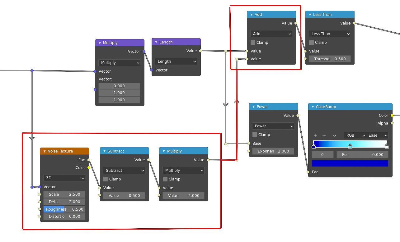
The Subtract and Multiply math nodes after the noise are there to remap the noise from the (approximately) 0..1 range output from the node, to a -1..1 range which makes tweaking the noise strength easier.
Try playing with those two math nodes to change the strength and shape of the output to get a feel for how it affects the result!
Note
It’s a good idea to keep the Detail parameter of the noise texture low, as increasing it makes the shader very expensive. You can always turn it up later if you need more detailed noise.
1.7. Step 5: Shader Setup - Distortion
Now that we’ve got our basic shape and noise, all we need to add to finish the effect is some stretching and twisting.
Let’s start off simple:
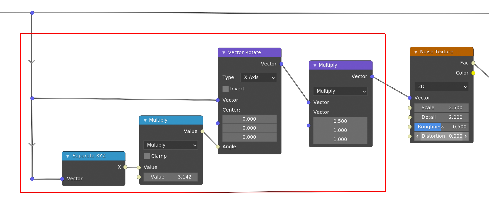
By plugging the X-coordinate value into the Vector Rotate node, we get a twisting effect - as you move along the mesh the X value increases, and so does the rotation. The 3.142 value is from typing pi into the value socket to get 1 full rotation along the length of the mesh, which would be needed if you want to tile the effect.
The Multiply vector math node just stretches the noise along the twisted X-axis for a less blobby look.
This is starting to look a lot better (and in fact, we’re basically finished) but it still doesn’t move!
Let’s add a few more nodes to offset the noise over time:
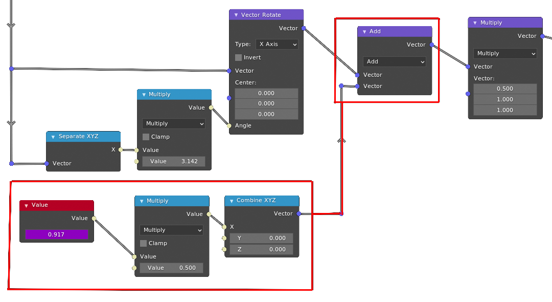
In the value node type #frame / 24 (replace 24 with your framerate if needed) to get a quick easy time input driver. The Multiply math node controls the speed of the motion.
And with that, we’re pretty much done. Here I reduced the Subtract after the noise by a small amount for emphasis, and increased the Detail of the noise to 4:
1.8. Extra: Example BEER GLSL Shader
I also made a slightly messy shader program, using BNPR’s BEER engine. There is much room for improvement, this is mainly here for reference and as a proof-of-concept.
Note
Edit 2021-01-05: Huge thanks to Miguel Pozo (Lead dev on BEER!) for tidying up some of this shader code.
1 2 3 4 5 6 7 8 9 10 11 12 13 14 15 16 17 18 19 20 21 22 23 24 25 26 27 28 29 30 31 32 33 34 35 36 37 38 39 40 41 42 43 44 45 46 47 48 49 50 51 52 53 54 55 56 57 58 59 60 61 62 63 64 65 66 67 68 69 70 71 72 73 74 75 76 77 78 79 80 81 82 83 84 85 86 87 88 89 90 91 92 93 94 95 96 97 98 99 100 101 102 103 104 105 106 107 108 109 110 111 112 113 114 115 116 117 118 119 | /*
Example BEER mesh shader, to be applied to a default cube.
Save as xxx.mesh.glsl in order to load it as a BEER material.
Authored by Lateasusual, improvements by Miguel Pozo (@pragma37)
*/
#include "Pipelines/NPR_Pipeline.glsl"
// Hash function from https://www.shadertoy.com/view/4sfGzS
float hash(vec3 p)
{
p = fract( p*0.3183099+.1 );
p *= 17.0;
return fract( p.x*p.y*p.z*(p.x+p.y+p.z) );
}
// Basic value noise
float noise( in vec3 x )
{
vec3 i = floor(x);
vec3 f = fract(x);
f = f*f*(3.0-2.0*f);
return mix(mix(mix( hash(i+vec3(0,0,0)),
hash(i+vec3(1,0,0)),f.x),
mix( hash(i+vec3(0,1,0)),
hash(i+vec3(1,1,0)),f.x),f.y),
mix(mix( hash(i+vec3(0,0,1)),
hash(i+vec3(1,0,1)),f.x),
mix( hash(i+vec3(0,1,1)),
hash(i+vec3(1,1,1)),f.x),f.y),f.z);
}
// Basic fractal value noise
float fracnoise(in vec3 pos) {
return noise(pos) * 0.5 +
noise(pos * 2.0) * 0.25 +
noise(pos * 4.0) * 0.125 +
noise(pos * 8.0) * 0.0625;
}
// Vector rotate - X
mat3 rotationX( in float angle ) {
return mat3(1.0, 0, 0,
0, cos(angle), -sin(angle),
0, sin(angle), cos(angle)
);
}
// Input parameters
uniform float speed = 1.0;
uniform float twist = PI;
uniform float noise_strength = 2.0;
uniform float edge_threshold = 0.25;
uniform float step_size = 0.04;
// Function to sample on each step - returns distance to center and alpha (whether hit or not).
vec4 noise_func(in vec3 rpos) {
// 2D gradient
float g = length(rpos.yz);
// Twist around X axis
vec3 p = rotationX(twist * rpos.x) * rpos;
float noisev = (fracnoise(p * vec3(2.5, 5.0, 5.0) + vec3(TIME * speed , 0.0,0.0)) - .5) * noise_strength;
float a = float((g + noisev) < edge_threshold);
return vec4(g, g, g, a);
}
// Check point is inside axis-aligned-signed-unit bounding box.
bool inBox2(vec3 v) {
return v == clamp(v, vec3(-1), vec3(1));
}
// Adjust this and `step_size` for performance.
uniform int steps = 128;
// Raymarch through noise function and return early on hit.
vec4 noise_step(in vec3 ro, in vec3 rdir) {
vec4 f;
for (int i = 0; i < steps; i++) {
ro += rdir;
if(!inBox2(ro)){
return vec4(0);
}
f = noise_func(ro);
if (f.a > 0) {
return f;
}
}
return f;
}
uniform sampler1D in_ramp;
void COMMON_PIXEL_SHADER(Surface S, inout PixelOutput PO)
{
// "Incoming" vector in world space (Incoming vector in eevee)
vec3 incoming = view_direction();
// Incoming vector in object space - ray direction.
vec3 rv = transform_normal(inverse(MODEL), incoming);
// Position in object space.
vec3 ro = transform_point(inverse(MODEL), S.position);
// Hit angle (shorten high-angle rays as a very basic optimization to slightly improve quality)
float rfac = dot(incoming * -1, S.normal);
float step_s = (1 / rfac) * step_size;
// Randomize initial step offset based on sampling to remove banding.
ro += rv * step_s * get_random(1);
// Perform raymarch
vec4 ca = noise_step(ro, rv * step_s);
// Sample colorramp texture and output.
PO.color.rgb = texture(in_ramp, ca.x).rgb;
PO.color.a = ca.a;
}
|